If you are all set for circuit board assembly, here is an important consideration: make sure that it is well-optimized for speed. The better is your circuit board’s rate, the more beautiful it will be in its performance. The faster the speed, the higher the work efficiency. It has excellent value for PCB production. If you do not have a way to improve efficiency, it may cause the product to fail to deliver appropriately.
So how can you make optimize your PCB and assembly? Here we make eight suggestions, Let’s find out.
Contents
- 1 Plan Well in Advance
- 2 Schematic Related Design Techniques/wiring (minimize routing and other issues)
- 3 Material and Stacking Requirements
- 4 Components Pick and Place
- 5 Find Ways to Shorten the Time Limit for Procurement Components
- 6 Pad and Pin Size
- 7 Production Process Collaboration Issues
- 8 Choosing Medium and Large-Scale Factories can Ensure the Efficiency of the Assembly Line.
- 9 Conclusion
Plan Well in Advance
The best way to optimize your PCB assembly is by planning. You must be clear about your requirements. From determining the target signal speed to analyzing the requirements in terms of sensitive signals, material requirements, Wait-everything should be kept safe.
Detailed documents will help suppliers to make assembly plans more quickly and purchase needed materials. Quick and precise preparation will speed up your assembly efficiency.
To further keep things organized and ensure the best turnkey PCB assembly, you must note down all the points to clear your requirements from the start.

Schematic Related Design Techniques/wiring (minimize routing and other issues)
To ensure a quick PCB assembly, It is essential to focus on schematic diagrams. Designing a schematic diagram helps the precise and accurate depiction of the circuitry flow and helps the engineers working on the board.
The schematic diagram provides a clear overview of the components required, clock lines, How differential pair routing, and other similar terms. And other related aspects. All this handy information equips engineers better and helps them decide the proper layout to achieve a high-speed PCB.
Clear PCB layout that you can provide to the supplier. When the PCB supplier obtains a clear PCB layout diagram, it can make a production plan more efficiently. THE chaotic PCB layout will cause the picture to be unclear and the structure complicated, and it will take some time to analyze. The PCB designer, in the beginning, is essential. It would help if you had a sound designer and communicate with your PCB supplier promptly.
All in all, it won’t be wrong to say that the schematic designing of your PCB is the first step that lays the foundation for a high-speed PCB design.
Material and Stacking Requirements
You will agree with us that your PCB’s performance, to a large extent, depends on the board materials and stack-up requirements. That is to say, and if you want to realize a high-speed board, you must make use of specialized materials and move over the standard PCB processes.
Some of the materials you should get your hands on including Rogers and FR-4. In addition to choosing specific things, they play a vital role even in stacked structures.
The best practices related to stack up include directing high-speed signals on the inner layers between planes, positioning a plane layer adjacent to a signal layer, using multiple ground planes in layer stack up, and the like. All these practices can optimize the speed of your PCB noticeably. Also, precise and straightforward material requirements can quickly realize PCB assembly.

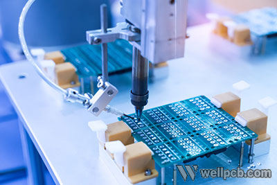
Components Pick and Place
Another best practice that you must stick to while designing and assembling your PCB. Follow the proven strategies related to high-speed PCBs instead of reinventing the wheel. Some of the best practices when it comes to placing your components include putting them in critical power locations or arranging individual circuits in a way such that it contributes to the course’s overall speed.
Before assembling the PCB, you need to check with the BOM file to ensure that each step is correct. We need to ensure that the PCB board’s production is consistent with the BOM file to avoid rework. Save time and get the job done efficiently.


Find Ways to Shorten the Time Limit for Procurement Components
Procuring the right components which could meet most of your requirements at the right time is essential. Look for manufacturers who can provide you with an accurate quote within a day and perform the entire turnkey process within 3 -5 business days.
You can send the BOM file to your PCB supplier a few days in advance. Some vendors can provide one-stop services, including the purchase of materials. The materials you need can be delivered to them, which can be used as PCB assembly, preparing documents in advance.
To ensure that your PCB is appropriately optimized for speed, ensure that you are sourcing the components from reputable suppliers in the industry.

Pad and Pin Size
The choice of Pad and pin size will affect the speed of PCB assembly and the rate of the PCB board function. So you need to pay special attention to this one.
The Pad and pin size and how to install it. When designing a PCB, you should communicate with your PCB designer in detail. Under the same conditions, If you can produce the same functions, we can choose the simplest. It can help later PCB assembly and proceed faster. The complex Pad and pin size will affect the aesthetics and the speed of PCB assembly.
Design tips:
Although standard PCB practice might recommend you to go for larger pads, this is one thing that you should refrain from if you are developing high-speed circuitry. It strongly recommended limiting the pad size to 0-5% of the component pin size. It will provide more space to position other differential pairs like integrated circuits and FPGAs. All these help in proper optimization of the speed of the board.

Production Process Collaboration Issues
To enable high-speed PCB assembly, it is essential to collaborate appropriately. The person working on the schematic might not be the one who is assembling. Thus, it is necessary to communicate well within the team and ensure that everything stays in the loop.
With your PCB supplier, ensure that the contact information is unobstructed so that if you have any questions, you can contact them in time. Suppliers are directly connected to the production plant, so the PCB’s efficient assembly cannot be separated from the timely communication between us, which is very important. For example, if you need to change the material temporarily, inform your PCB supplier in time to make the changes as quickly and efficiently as you want. Avoid rework after PCB assembly is complete.

Choosing Medium and Large-Scale Factories can Ensure the Efficiency of the Assembly Line.
Ultimately, The speed of PCB assembly depends on you choosing the right factory. Ideally, it would help if you decided to go for medium and large-scale factories to ensure maximum efficiency.
Professional staff in every department of the factory This will ensure that you don’t lose efficiency due to non-professional Further. More often than not, large manufacturing units have a dedicated specialized department for each process. Undoubtedly, it confirms complete professionalism and efficiency.
You can rest assured that not only the performance of the PCB is optimized, but also designed and assembled following the prescribed time frame without any delay. It’s essential, especially if you have other processes that rely on PCB assembly.

Conclusion
Following the above steps, you will be able to optimize PCB assembly for performance and speed. Care should be taken to plan, use the right materials, and adopt the proper stacking techniques. The right pad and pin size also play a vital role in determining the speed of the PCB.
For the best PCB assembly service, please contact us immediately. We adopt proven strategies and ensure that our electronics assembly services are the best. For more information, contact us now.