Do you want to try Flex-rigid PCB, but you are afraid of the potential performance issues and problems during the assembly process?
As long as you ensure the design and manufacturing process go smoothly, you will receive a reliable and high-performing printed circuit board.
Check out essential tips and considerations that can help you to streamline assembly and improve the reliability of flexible and flex-rigid PCBs!
Contents
- 1 The Difference Between Flex-Rigid and Flexible PCBs
- 2 How to Choose the Right Material
- 3 Flex-rigid PCB – How do We Choose Normal Equipment
- 4
- 5 Flex-rigid PCB – The Importance of Stack Management
- 6 Flex-rigid PCB–Ground Plane Integrity
- 7 Flex-rigid PCB–Bend Management
- 8 Flex-rigid PCB–Trace Management
- 9 Conclusion
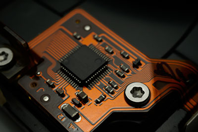
The Difference Between Flex-Rigid and Flexible PCBs
Here is a basic overview if you need a reminder. You have three basic printed circuit board types – rigid, flexible, and flex-rigid.
Rigid boards are also famous as ordinary. Although they are far from being a thing of the past, flexibility is the latest breakthrough in the PCB industry. As a result, we have both flex-rigid and flexible PCBs.
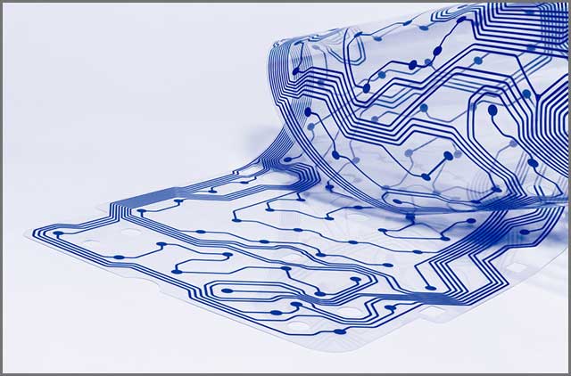
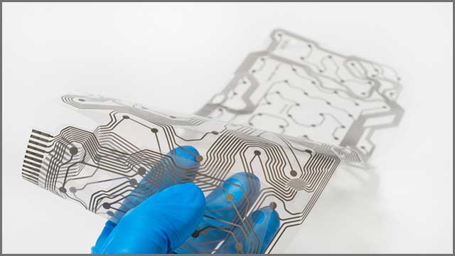
Flex-rigid boards combine rigid and flexible layers, and flex boards stick to using only flexible components. In other words, flexible PCBs are those that offer total flexibility. The choice ultimately depends on you and your application’s requirements.
Take a look at some advantages that using flex and flex-rigid boards bring:
- Flexibility – the most significant benefit is that you can fit them in unusual spaces and almost any design.
- High-density layouts – putting fewer components in a crowded area ensures reduced weight and size of your boards.
- Reduced overall cost – the fact that you design smaller and thinner boards than conventional PCBs will reduce the project’s total cost.
- Improved reliability – these boards already have better security than ordinary boards.
How to Choose the Right Material
If you want your printed circuit board to perform well, you want to choose high-quality materials. Let’s take a quick look at some necessary materials used for flexible PCBs:
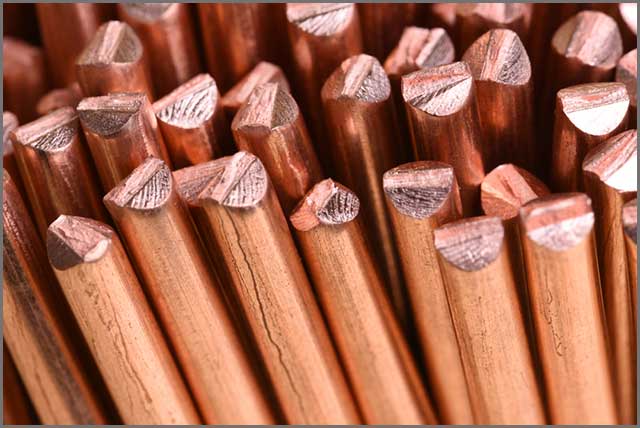
• Polyimide – it is the most popular substrate material. A beautiful combination of decent characteristics and low cost makes it particularly attractive.
• PEEK – it is an abbreviation for polyether ether ketone. The content itself is not pure PEEK but based on it. Excellent resistance to temperature and radiation is why we see this material in advanced applications.
• PTFE – it is short for polytetrafluoroethylene, but it is famous as Teflon in pans. It handles high temperatures well and features low dissipation.
• You also need to consider cladding, conducting, and other materials required to design your boards.
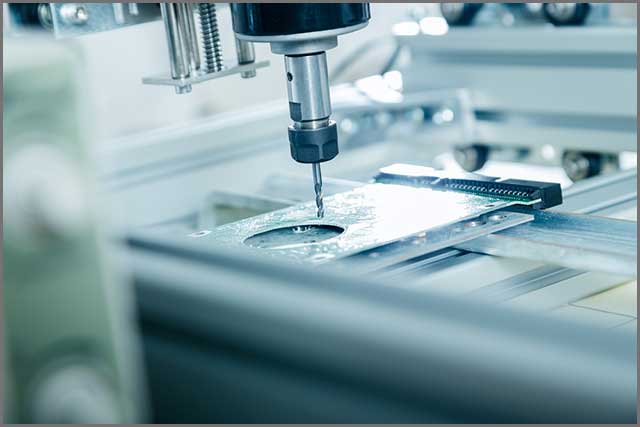
Flex-rigid PCB – How do We Choose Normal Equipment
Assembling your flexible PCB on state-of-the-art machines is essential for its performance and reliability. You can have premium quality materials and the best possible design. It won’t do you any good if you don’t take advantage of modern equipment.
Only the best PCB companies make sure to use the latest equipment and gather experience staff. One of those companies is WellPCB, which has been serving users in various industries for years.
The expert staff knowledge and experience guarantee that you will always have the best solution for your desired application. The assembly will be quick and streamlined, which means you will receive your boards in the shortest possible timeframe.

Flex-rigid PCB – The Importance of Stack Management
One of the crucial considerations of flexible PCB design is stack management. If you define your stack up correctly, it will secure your board’s flawless assembly and performance. If you put it like that, it sounds simple. However, defining a precise template is not an easy job.
Apart from the required knowledge in using appropriate design software, experience plays a crucial role in stackup management. Only through experience and learning, stacks work well that you can learn to design reliable PCBs.
Designers will face different challenges throughout the design process. They need to avoid any flaws in the design itself. Those may include inadequate fabricator communication and overall inefficient management, which can affect your board’s performance.
Additionally, it would help if you considered that your design is doable in practice. That means that the manufacturer can pull it off with the equipment and materials available today. Although premium companies use the best machines and tools, not everything you draw in a program is doable in practice.
It is needless to say, but you need to use specialized software made for designing PCBs. Aim for tools that offer 3D design support to enable you to double-check component placement and bend integrity.
It would help if you also considered hiring an expert to handle stackup management. It is a wise
move if you want to ensure optimal stack up of your board.

Flex-rigid PCB–Ground Plane Integrity
It is time to make a difference between two types of flexibility in printed circuit boards:
• Dynamic flexion
it is standard flexibility, which means that the board will need to fold and bend whenever the product is used.
• Flex-to-install PCB
As the name suggests, you only need flexibility and bendiness during the installation process. As soon as you put the board into the designed place, it stops utilizing its elastic properties.
If you compare the design of these two types, it will be easier to design a flex-to-install board. Because you only need to consider mechanically stressing ground planes while setting up the board.
A flexible PCB with dynamic flexion needs to have an adequate signal and ground-plane integrity. It would help if you focused on substrate materials and kept in mind the integrity of the message.
One of the ways is to use ground planes made of solid copper. They can serve routing circuits in boards with dynamic flexion. Although they are suitable for high-speed circuits, unbroken copper on flexible layers may lead to failure and cracking.
The alternative can be nickel and gold plating, but you will also face a risk of mechanical stress and fractures if you apply it to flexible components. Where is the solution then?
The experts recommend going with annealed copper as it can increase ground-plane integrity. The problem is that it is a costly solution, and it may not be suitable for everyone. That is why you should analyze where you need the highest signal integrity on ground planes and only put annealed copper there.
You have another alternative – utilizing ground planes of cross-hatched polygon type. Although that will boost flexibility, high-speed signals may suffer. You may improve them by using stable return paths underneath traces with high speed. Keep in mind that you should keep them at least five times widen compared to signal traces.
Flex-rigid PCB–Bend Management
If you plan on carrying ground planes on power on your boards’ flexible layers, you shouldn’t worry only about trace routing. Those going with a design that needs to fold repeatedly will need to consider through-holes and surface-mounted pads, too.
Plated through-holes are almost standard when designing flexible PCBs. The industry experts emphasize the importance of anchoring them with extra overlay when it comes to the pads. It can increase the strength and reliability of the board.
If you are going for a flex-rigid PCB, you want to avoid placing vias or components near the bends. If you put the bows under repeated mechanical stress, you may affect the performance of vias and components nearby. That may decrease the reliability and durability of the board.
Here are some tips you can apply when it comes to bending management:
Make sure the bending is not tighter than necessary
It would help if you aimed to use thicker materials at bend areas
The articles you choose for bending shouldn’t stretch as that can lead to failure of the board
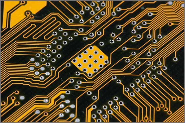
Flex-rigid PCB–Trace Management
The final thing we will discuss is how to design your traces. Please take a look at your bend and place them perpendicular to it. It is particularly essential to route them like that in flex-rigid PCBs because you will decrease trace stress. If you are using a double-sided design, consider offsetting the traces.
Monitor the circuit’s bottom and top, and stagger the traces in those two positions. That way, you will achieve more consistency and resistance to continuous bending and mechanical stress. Your boards will be stronger and more reliable.
Here is another crucial tip – using a 90-degree angle when bending traces is not something experts recommend. You want to aim for curved marks to withstand stress better. Also, by using a segmented linear curve when setting up the trace. You can minimize the risk of delamination.
For flex-rigid boards, you should avoid circular pads and stick to teardrop ones. That will secure easy drilling and strengthen the substrate base material. If necessary, you can use anchor stubs for additional support, especially if you are unsure about copper adhesion.
As for the traces’ layout, you want to keep a constant impedance of the signal path along the complete length. Aim to specify the mark that will suit both the flexible and rigid layers of your board.

Conclusion
As you can see, improving your flex-rigid and flexible boards’ reliability is not an easy task. Fortunately, it is something you can do as long as you take care of every step of the process.
Everything starts with the design, as that is where you streamline the assembly. If you need any help, do not hesitate to contact professional engineers who can resolve any dilemma you might have! Making the right decisions regarding the materials, stackup management, and other factors, will only enhance your PCB performance.


