Contents
What is Flexible Electronics
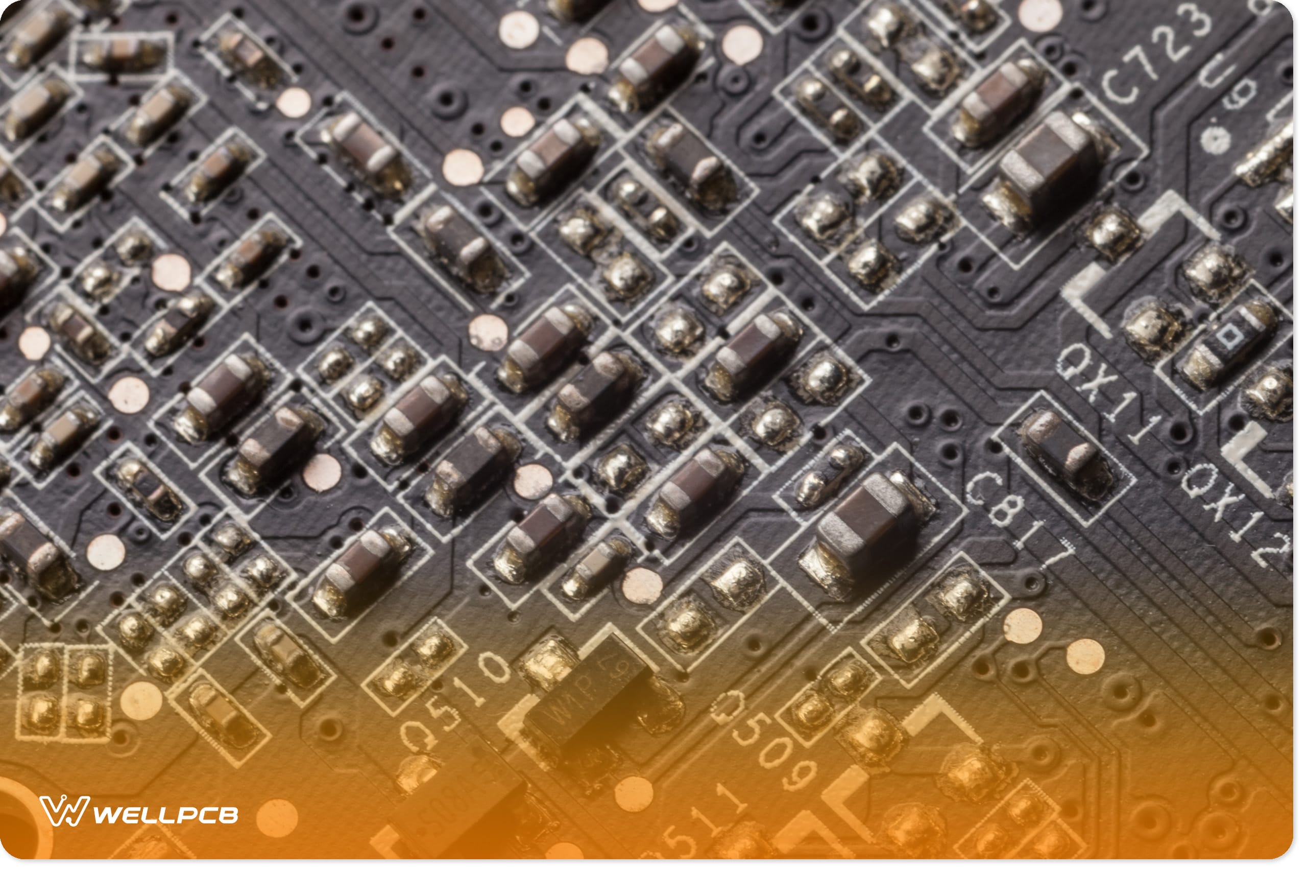
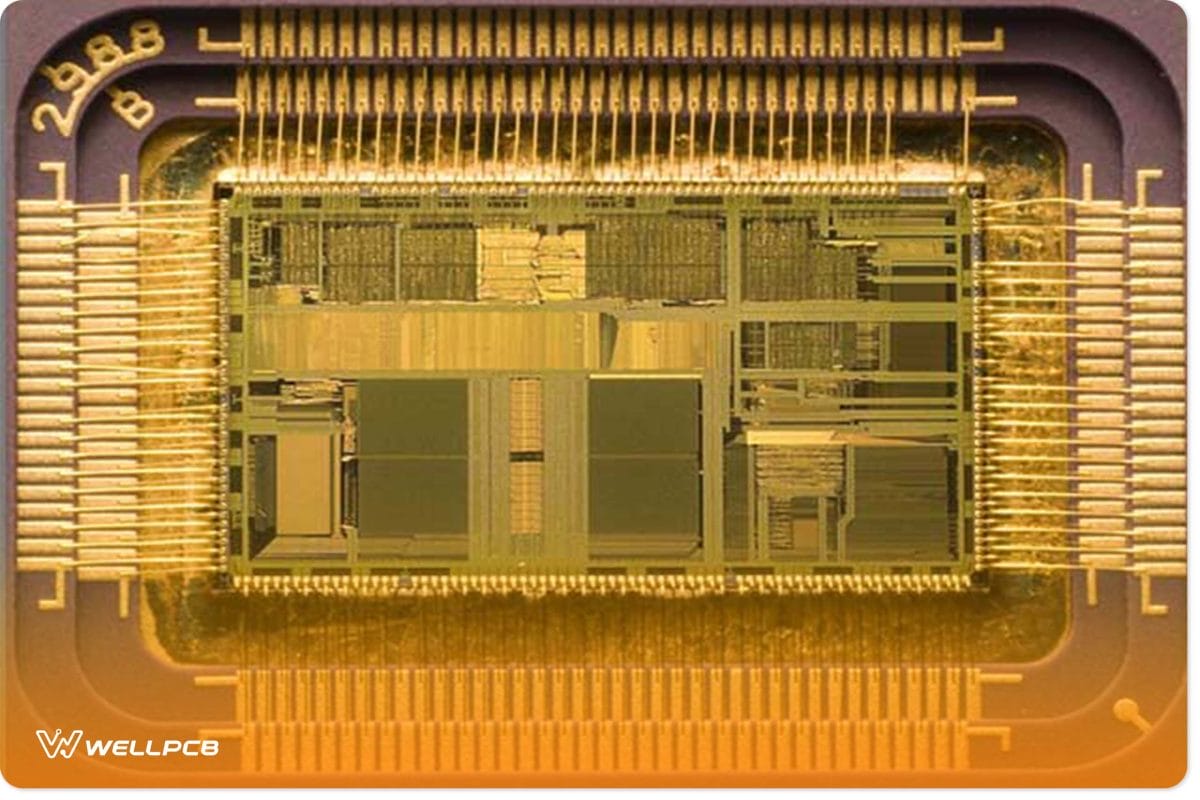
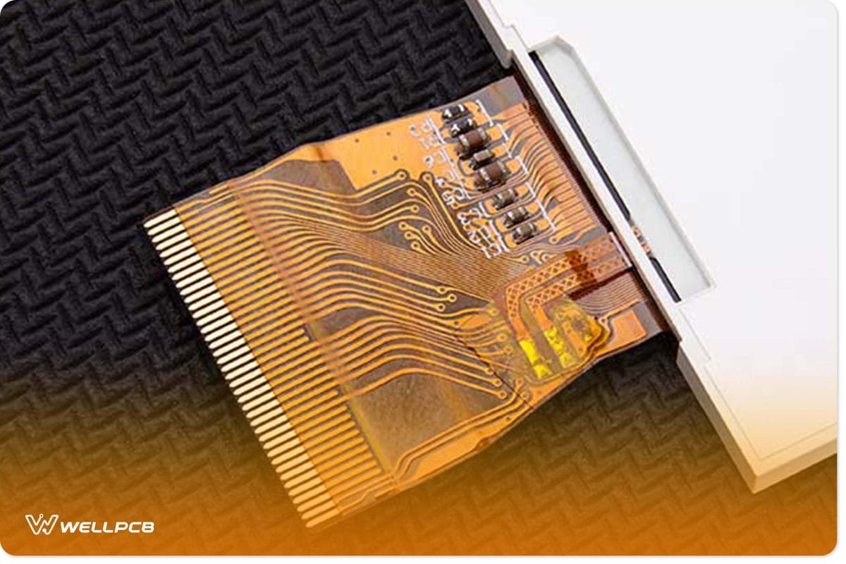
Flexible electronics, also called flex circuits, comprise electronic devices mounted on flexible plastic substrates like conductive polyester films.
The electronic components of flexible electronics are identical to those of rigid PCBs. But even more importantly, the flexibility of flexible electronics creates a whole world of difference between flexible electronics and PCBs.
Other popular plastic substrate materials that you can use for flexible circuit boards include polyimide and PEEK. You can also use silicon substrates that are thinned out through etching techniques. By so doing, you imbue the silicon substrates with great flexibility.
And such a degree of flexibility invariably opens a whole new world of possibilities.
Applications of Flexible Electronics
The rigidity of PCBs imposes limitations on their suitability in applications where flexibility, space efficiency, and cost-effectiveness are of critical importance. An example of such applications is electronic systems, which require three axes of electrical connections, like in cameras.
In these instances, FCB electronics are the best bet. The following is a rundown of key areas you should know of where FCB electronics lend themselves to great use:
Computer systems
Flexible electronics compose the moving print head of printers. They’re also used to relay signals sent to the satisfying arm-bearing disk drives’ read/write charges. Flexible electronics are also used to create the switch matrix in computer keyboards.
LCD Technology
The flexible plastic substrate of flexible electronics can serve as a great alternative to glass in LCD production. This imbues the entire system with ample flexibility, as the film atop the substrate is usually a few micrometers thick.
Organic Light-Emitting Diodes (OLEDs) Technology
OLEDs are lauded alternatives to backlights due to their flexible display attributes. You can enhance the serviceability of OLEDs by making them even more flexible.
Electronic Assemblies
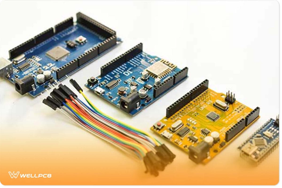
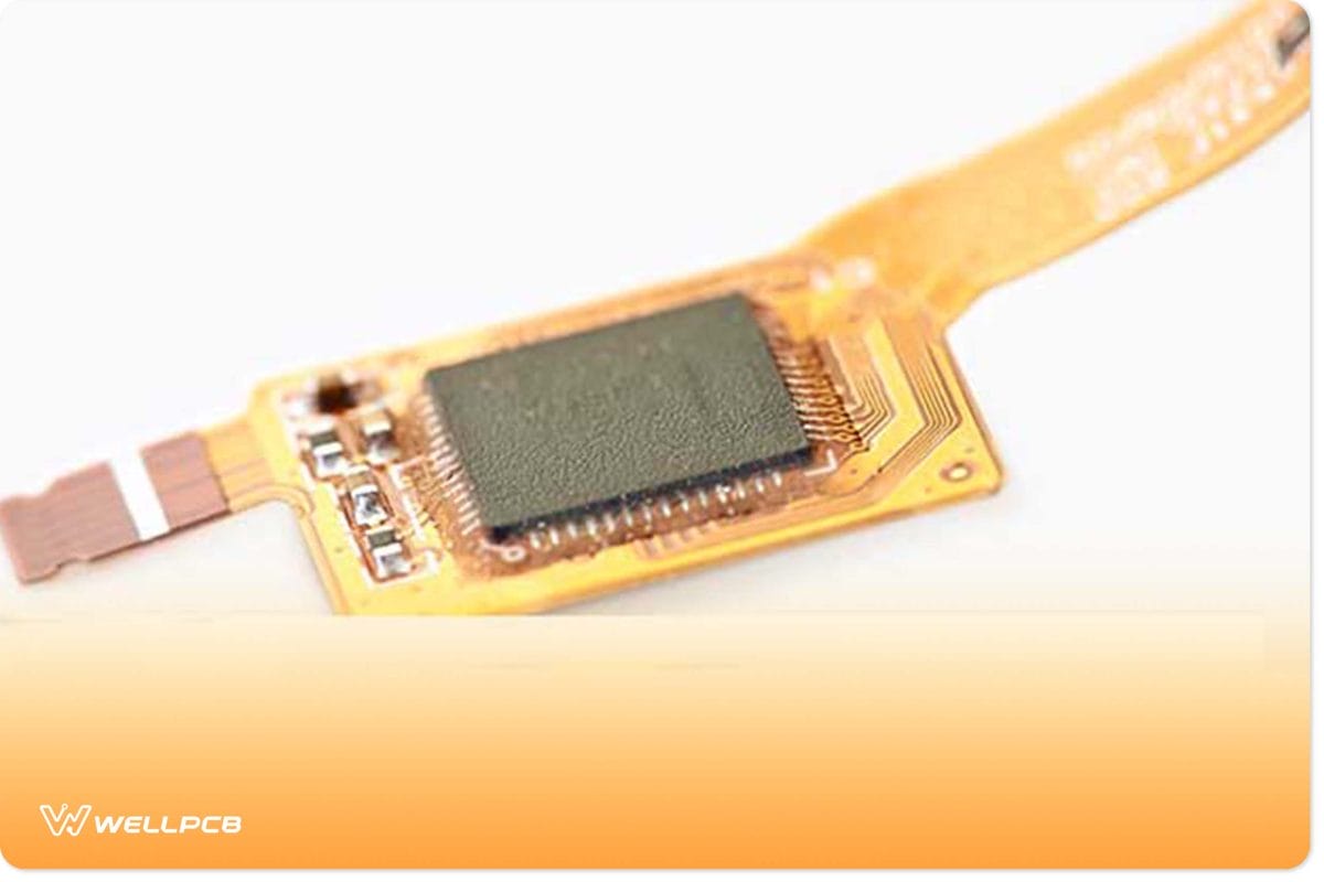
Flexible circuit boards provide a means for connecting electronic components such as resistors, capacitors, integrated circuits, etc. However, their applicability can also provide a means for interconnecting multiple electronic assemblies directly or through connectors.
Automobiles
Flexible electronics lend themselves to several uses in automobiles. Compartments such as the under-hood controls, ABS systems, instrument panels, etc., can all tap into the virtues of flexible circuits.
Consumer Electronics Devices
From cameras to entertainment systems and wearables, there is a slew of consumer electronics that FCBs provide excellent serviceability.
Industrial Applications
Industrial devices, including medical and sensor devices, all have varying needs for flexible, interconnected electrical circuits.
Solar Cells
Flexible solar cells have already gained wide use in powering satellites. In addition to being lightweight, they can also be easily folded before launch and then deployed mid-flight.
Sounds good? Well, wait until you learn more about flexible electronics in the following chapter.
What is FPC in Electronics?
Fabricated printed circuits (FPC) are flexible electronics with a protective coating that enhances their performance. They usually comprise a thin, insulating polymer film hosting electronic circuits of various patterns.
These electric circuits are couched in a thin polymer coating or any similar coating or laminations that offer an extra layer of protection. You can also make FPC electronics using photolithographic technology.
There are many non-conductive insulating materials that you can use to protect the circuit from electrical interference, wear, and weather. They all have their distinct advantages and disadvantages that make each one better suited to specific applications.
So, since you can make FCB electronics using various methods, you need to have a comprehensive understanding of the multiple types of FPC. The most popular types of FPCs are the single-layer, double-sided, and multilayer FPCs.
With a thorough knowledge of the various types of FPCs, you’ll be better equipped to harness the advantages of FPCs. By doing so, you’ll be able to trump the many limitations of PCBs since FPCs can host the same electronic components as PCBs do.
Some of the applications wherein FPC holds a greater over PCBs include:
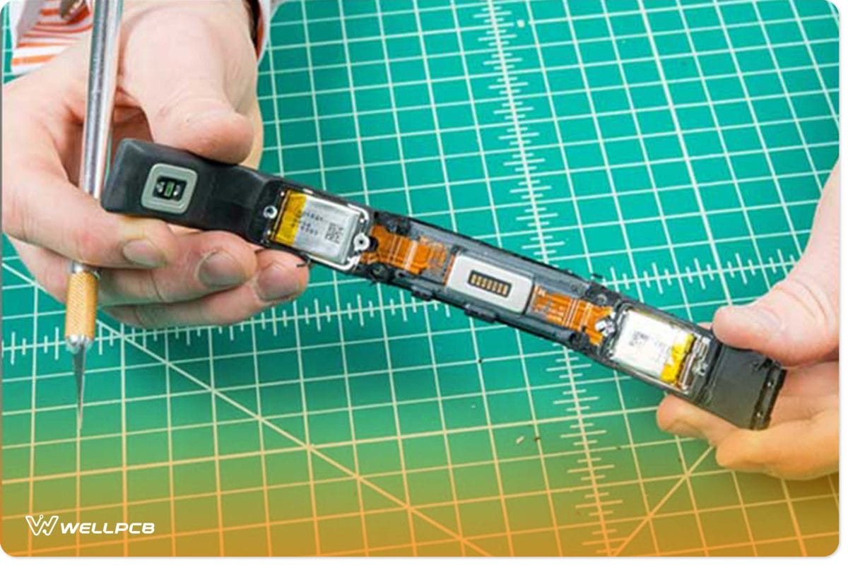
- Electronics with compact, portable packages where electrical connections must hold in 3 axes, such as in cameras.
- Electronic devices that must fold or bend during normal use.
- Electrical assemblies that require interconnections between sub-assemblies, such as the electrical systems in cars, satellites, and on-premises technological installations. In these cases, FCBs are even lighter and more efficient than wire harnesses.
- A host of other electrical appliances where space efficiency and weightiness are key considerations.
The list continues to grow by the day as technology continues to advance. But to forge valid future expectations for this technology, you need to understand its evolution thus far.
The Evolution of FPC Electronics
A semblance of a printed flex circuit board first surfaced as an outcome of Galileo’s experiments. His conception of a would-be FCB electronic featured a piece of paper with paraffin coating hosting a flat metal conductor.
Throughout the centuries afterward, theories of flexible circuits kept flying around in great circles. Thomas Edison once expounded a notion hinting at flexible circuits in one of his books.
His proposition centered around coating linen paper with a mixture of pattern cellulose gum and graphite powder.
In the 1950s, Roger Curtis and Cleo Brunetti expounded on insulating materials suitable for use in the fabrication of flexible circuits. During that same period, the Photo Circuits Corporation disclosed their ground-breaking findings on FPC electronics.
Another major break came when Victor Dahlgren and Royden Sanders were poised to replace harnesses with a setup akin to flexible circuits. A crop of Japanese engineers increased the technology’s applicability.
You’ll find vestiges of these early works on every piece of modern-day FCB electronics. But unlike what you see in the earlier versions of flex circuits, the modern-day flex circuit technology integrates both active and passive functions.
Advantages of FPC Electronics
- It can serve as a viable replacement for multiple stiff boards and connectors.
- Single-sided circuits are well-suited for use in devices with flexible form factors.
- They can be stacked in various configurations.
Disadvantages of FPC Electronics
- It may turn out to be costlier than rigid PCBs in some configurations.
- It might be more susceptible to damage in certain applications.
- It makes the assembly process more complicated.
- You may find it more difficult or untenable to repair.
FPC PCB
They can both complement and substitute each other in some instances. But you need to note that FCBs have a more comprehensive range of applicability than PCBs.
A Printed circuit board, or PCB, is a board that hosts electrical circuitry. With its multiple layers, it can perform various functions simultaneously and handle high-current transmissions.
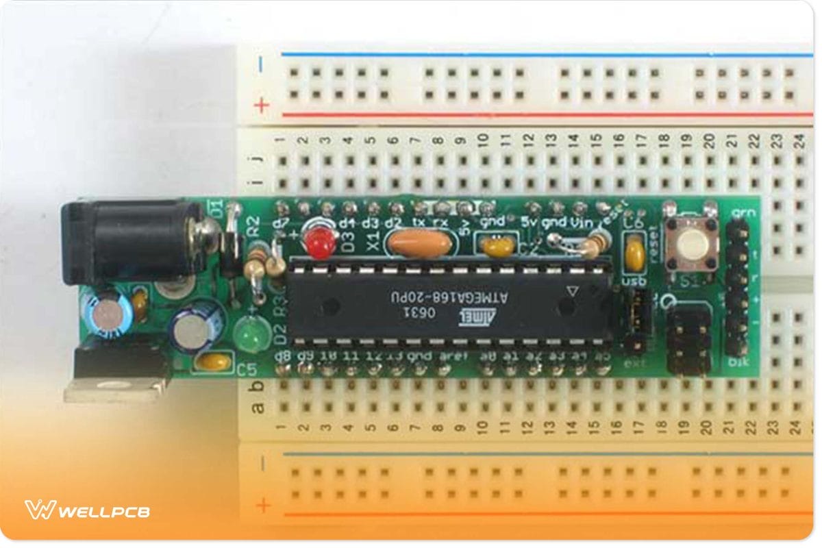
Of course, by now, you already know the significant difference between the two is the materials on which you print the circuit. Theoretically, the difference is instead of etching the prints on a rigid board; you print on a flexible plastic sheet.
But the “plastic” sheet isn’t just a simple material.
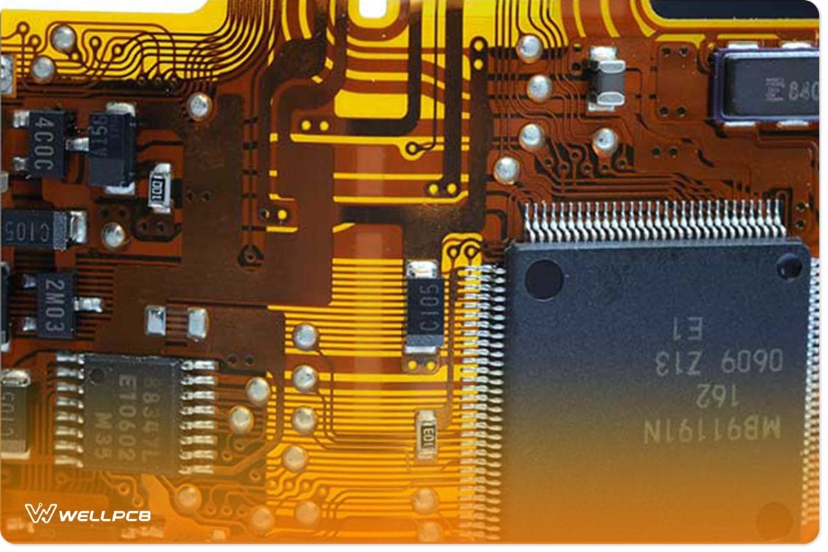
The structure of the sheets is much more complicated. It features copper films and other conductive “traces” like silver traces printed on a flexible surface.
Also, the “traces” on the plastic have a very complex makeup, even though they look like inks in plain sight. These “traces” comprise materials that are better conductors of electricity than wires and soldering. The qualities of these complex materials make for an easy-to-use device.
But whether you’re fabricating PBC or FPC electronics, two crucial things determine the application’s quality. First is the quality of the materials, and the second is the PBC tools and assembling procedures.
One of the most efficient ways to assemble PBCs and FPCs is by pressing a ‘hot-bar’ device across all terminals and soldering them simultaneously. If you can’t use the ‘hot-bar’ device, you can opt for the pulse-heated reflow method. Pulse-heated reflow is a soldering process that entails heating pre-fluxed, solder-coated parts to melt, flow and solidify into new structures.
Now, we’ll let you take a closer look at the heat reflow process in the following chapter.
Soldering FPC to PCB
Pulse-heated reflow is a process wherein pre-fluxed, solder-coated components undergo heating to bond the parts with the solder.
In this procedure, you get to heat the parts until their solder melts and flows. And when the melted solder solidifies, it forms permanent electrochemical bonds with the details.
The significant difference between pulse-heated soldering and the traditional soldering process is that the former uses the mode. A thermos is a heating element that undergoes a heating and cooling cycle under a certain pressure for each solder connection.
The thermode, sitting atop the reflow soldering head, receives energy through a pulse-heated control. It also provides feedback on the power to enable consistent heat application.
The soldering head facilitates grinding contacts between the two parts. When the pressure is sufficient, the head induces the control to trigger the heating cycle for the thermode.
The thermode transfers heat to the parts to melt the solder in between the parts. As the molten solders begin to flow, they create a coalescence between the solder areas of the two regions. The coalescing solders are cool and re-solidify to form new joints after the reflow cycle ends.
For the solder joint to be good enough, it must join both surfaces and cause wetting (solder flow) on the covers of both parts. Also, the solder gravitates to the sides of the details when it melts. Hence, the flexible circuit pad must have a smaller width than the PCB pads.
This configuration creates space on the sides of the flex pad for the soldiers to flow into. This allows the flex pad to accommodate the quantity of the PCB’s solder without any complications.
The Key Characteristics of Pulse Heated Reflow Soldering
The rules that govern the pulse-heated reflow procedure are different from those that guide traditional soldering. For starters, the joint design and control over the solder quantities are vital to successful soldering in reflow.
The collaborative design plays a crucial role in determining how broad the process window will be. It can also accommodate the solder flows to compensate for any inconsistencies that occur during the prior processing.
Also, the control over the thermode soldering cycle helps you to miniaturize and reduce the weight of the circuitry pads.
Following is a breakdown of the critical aspects of the healing process in pulse-heated reflow soldering.
Preheat
You can get a modern thermode that measures up to 2” in length to reach soldering temperature in two seconds. Within that period, the thermode removes the oxide layer to induce wetting.
Nonetheless, preheating is only appropriate when excessive heat sinks affect the thermode and when the application comes with delicate substrates.
Rise
The average rise time for thermoses is 1.5 – 2 seconds. But you can program the rise time to control the heating rate more precisely.
Reflow
You can also program this phase. You can program the time in 0.1-second increments and the temperature in 1-degree increments. The typical temperature in the contact area between the open solder joint and the thermode is 280 – 330C.
However, since the thermode experiences thermal transfer losses, you must heat it to a higher temperature. Its temperature must rise beyond 180C, at which point the solder begins to reflow.
Nonetheless, it would help if you used the minimum time and temperature. This minimizes the chances of damage and gives you greater control over the formation of the joint.
Cool
You can also program the cool temperature to end the heating process when the solder solidifies to form the joints. You can achieve this by programming the power supply to flip the relay, which controls airflow to reduce temperatures.
Because most circuitry pads have a much higher heat sink, the solder will have a lower temperature than the thermode. It’s, therefore, advisable for you to program the release temperature to 180C. At this ideal temperature, the chances of running into a dry point are negligible.
Now, so far, we’ve examined the processes of combining FPC and PCB boards in electronics. But are you ready to learn more about the methods of assembling electric circuitry?
PCB & FPC & PCBA
A Printed Circuit Board Assembly) is a board presented after the entire parts and components get soldered and rightfully installed. A PCBA, or printed circuit board assembly, is the board that bears the soldered and installed features of a PCB to accomplish the intended electronic functions which the PCB was designed for.
A PCB Rapid Prototyping. You can obtain a Printed Circuit Board Assembly) which is a board presented after the entire parts and components get soldered and rightfully installed. A PCBA after installing various features on the PCB according to the application you want to create. 3D PCB Printing makes the PCB and does the Printed Circuit Board Assembly (PCBA, therefore, requires a different set of materials than a PCB. The bill of materials for a PCB Rapid Prototyping. 3D PCB Printing makes the PCB and does the Printed Circuit Board Assembly (PCBA includes resistors, Integrated Circuits, transistors, capacitors, etc.
One of the most widely used methods you can use to obtain the production film work you require to manufacture PCBs. In the case of PCBA is through reflow furnace heating. This process establishes a mechanical connection between the PCB and the electronic components.
It ingrains traces and conductive pathways in the non-conductive substrates of the coated copper sheets of PBCs.
Another major step in the printed circuit board assembly process is exporting the components list from the design file of the PBC. After doing this, you can prepare the components independently or have a PCBA factory prepare them.
You can use some PCB tools to solder the components manually. You can also use a pick-and-place machine to place the PCB or FPC in a reflow oven.
The Difference in The Fabrication Processes of PCBs and PCBA
The processes of fabricating a circuit board are very different from electric circuit assembly processes. The fabrication of circuitry pads usually entails developing the boards, coating the substrates, and designing the FPC or PCB prototypes.
Nonetheless, it’s imperative to make the best choices of materials for FPCs, PCBs, and PCBA. But the PCB or FPC design selection becomes even more critical in the PCB assembly than in the PCB fabrication.
The processes used in assembling the components of a PCB or FPC depend on the chosen design of the electric circuit.
Types of Methods for Assembling PCB and FPC Electronic Components
Basically, all the methods for assembling FPC and PCB electronics components can be grouped into two categories:
The hole-through technique, where the members take their places in the gaps, and the surface mount technique (SMT), where the components are integrated into the outer sections of the electronic board.
Nonetheless, it would help if you used automated PCB tools to assemble PCBs when there are too many components for it. You can use machine placement that enables you to deploy bulk wave etching or reflow ovens.
But you can always use manual etching for small-scale PCBA.
Conclusion
Flexible electronics have opened us up to a whole new world of possibilities. We can now think of having roll-able entertainment devices, foldaway smartphones, transparent RFID, e-papers, etc., as viable consumer electronics.
FPC electronics hold the advantages of cost-effectiveness, light-weights, and shape-ability over the current silicon technologies. Hence, they’re poised to power the next generation of lightweight, portable, cost-effective consumer electronics.
Circuit board shopping, various things might get you confused. And we’ve been at the forefront of this development. We have the expertise and facilities to push you over the edge of the future of flexible electronics. Whether you are going for a single-sided PCB, a double-sided PCB, or any other type of PCB, You can Contact us today and help us make the immense possibilities of FPC electronics a reality.