Contents
- 1 Printed Circuit Assembly Best Design Software
- 2 Use DFM to Find Printed Circuit Assembly Manufacturing Problems
- 3 Printed Circuit Assembly Coating Effect
- 4 Printed Circuit Assembly Component Placement and Spacing
- 5 Printed Circuit Assembly Minimizes Trace Length
- 6 Design the Correct PCB Size and Shape
- 7 Design of PCB Layers
- 8 Through-hole Problem
- 9 Correctly Export the Bom File
- 10 Conclusion
Printed Circuit Assembly Best Design Software
Printed Circuit Assembly Before the discovery of PCBs, engineers use external wires to build reliable connections. However, things are more natural; there are many tools and software that you can use for PCB designing. Some are online, while others are offline. They have different features and usability. Some include:
1.EAGLE (Easily Applicable Graphical Layout Editor)
It is CAD software that is very popular among PCB designers. It has an easy-to-understand interface, and it is a useful software that contains a library that houses numerous electrical components.
EAGLE has two editors, namely: schematic editor and PCB layout editor. You can use the former to add all components and connect depending on the board requirements. The PCB layout editor has excellent features, including routing engine and alignment tools. Another feature of PCB design software.
1. PCB123
2. EAGLE that makes it accessible is it is free and paid versions. It implies that you can opt to upgrade to the paid version and if you not, you can still enjoy some great free features.
2.KiCAD
It is another popular PCB design software that you can use freely with no license requirements. As a PCB designer, you can use this software to create a bill of materials (BoM) and Gerber file. It has an extensive library that contains many electronic components. Another excellent feature is that it provides a 3D layout of the PCB.
3.Multisim
It is common among researchers because it has unique simulation capabilities essential for research. It is an easy-to-use software with outstanding features that portray high-end technology.

Use DFM to Find Printed Circuit Assembly Manufacturing Problems
Wne need to avoid wasting money, time, and resources, and it is essential to know some DFM (design for manufacture) tips. Finding the issues or problems of manufacturing in the early stages helps save a lot and ensure a smooth sail to PCB assembly and packaging stages. Some common problems include:
1.Slivers and islands
These are free-floating copper that can wreak havoc on the acid tank. If they are small, they float and cause a short. But if they cannot swim, they can create different interference, which can be burdensome. Some software can locate them in your designs, but if the software you are using is incapable of detecting slivers and islands, you might have to find them manually.
2.Heat sinks
It helps absorbs and dissipates heat from an electrical component. This heat dissipation is possible because the heat sinks come in contact with a metal base material. However, parts can float off the heat pads if the paste mask openings are enormous in the heat sinks. You can prevent this by making smaller paste mask openings in different points instead of making a large one in a single place. To get the accurate paste mask openings size, you must circuit board shopping, various things might get you confused. Whether you are going for a single-sided PCB, a double-sided PCB, or any other type of PCB, You can contact your PCB manufacturer.
3.Acid traps
These are sharp corners in your trace pattern that can trap harmful chemical etchants that you use to remove excess copper from a printed board during the manufacturing process. They can be skinny, and this makes them cause openings in the board designs. You can use some software to detect acid traps, but you might have to do it manually if you don’t have such software.

Printed Circuit Assembly Coating Effect
Before you embark on PCB assembly, you must know the current impact of PCB coating on your board designs. To avoid the unnecessary wastage of money, time, and resources that you could avoid, you must know the potential pitfalls of the choice of coating you use in your PCB manufacturing process and the mode of application.
We make sure you get the best PCB; it is essential to stick to an experienced manufacturer who will follow your PCB designs’ requirements to the letter instead of switching from one manufacturer to another.
There are different PCB surface coatings and different methods of application. By ensuring that your PCB design gets the best coating type is essential because this can cause a problem if you don’t monitor it closely. To save costs, don’t opt for shortcuts because you might end up spending double or more.

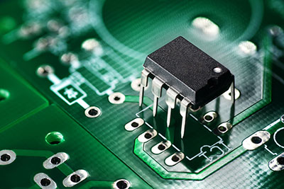
Printed Circuit Assembly Component Placement and Spacing
Before you get to the drawing helps to understand and run the board for the team members. The component symbols made for PCB layout and finally printed over the PCB board are helpful during PCB assembly phase, you must ensure you fix all PCB component placement and spacing issues to avoid incurring costs that you could avoid. As a PCB designer or assembler, there is no 100% way to place components, allowing you to get creative. However, you must be careful while doing this to avoid making routing errors.
If you don’t take careful measures while placing the components, you might eventually waste time as some parts may not have enough spacing for routing, and you might have to start all over again. Also, the manufacturer may return your boards to you if you place the components haphazardly. It can also give your board an ugly outlook, as it will show your lack of proper symmetry and accuracy.
To avoid component placement and spacing issues, you need to understand a couple of things:
1.Mechanical constraints:
know the right placement of edge connectors, mounting holes, amongst others. It will enable you the correct size and shape of your printed board.
2.Place similar components in the same direction
In case you are working with Surface Mount components or SMDs which require a wave soldering process, you must place similar elements in the same direction as it will make it easy for the PCB assembler to install, inspect, and test.
3.Dododon’t overlap any parts
While placing the components on your board, ensure to avoid overlapping the pieces to prevent short circuits. If you are working with a small or large commission, leave enough space between each piece because it will give you time to route all the copper traces.

Printed Circuit Assembly Minimizes Trace Length
By minimizing the trace length, you will reduce the EMI (Electromagnetic Interference) risks of your PCBs. Long traces leave your boards looking distasteful and cause EMI risks. The best way to minimize trace length is to layout our boards carefully.
Ensure to keep high-speed systems close to one another and the signal input to the receiver path. Using software capable of routing and rerouting traces to shorter lengths will make it look less burdensome.


Design the Correct PCB Size and Shape
It is another crucial aspect that requires attention because it usually determines the end-result of your PCB assembly. Choosing the wrong size or shape can alter your PCB design and give you a product different from your plan.
Various sizes and shapes of boards meet specific needs, and choosing the wrong one might not suit your PCB needs. Ensure that you select the right size and shape of boards that suit your PCB needs as the board for a wristwatch differs from a commission for a computer.

Design of PCB Layers
There are various PCB layers’ designs, and the design you want determines the PCB layer you will use. Single-layer boards include a solder mask layer, a solder paste layer, a mechanical layer, and a routing layer. Multilayer boards include many routing layers, ground planes, power planes, amongst others. Some boards have up to 4, 6, or 12 sheets. Understand the purpose of each segment and use the one that suits your PCB needs.

Through-hole Problem
It is not uncommon to encounter through-hole problems in the assembly process of PCBs. In plating through holes, you might create plating voids that prevent electrical currents from passing through the circuit, air bubbles, and other contamination forms. You can avoid this problem by preheating the printed boards to remove excess moisture and ensuring that the copper plating has a minimum thickness of 25um in the through-holes.

Correctly Export the Bom File
A bill of material (BOM) is the comprehensive list of all raw materials, components, assemblies, and other essential product manufacturing materials. The correct exporting of the Bill of Materials (BoM) will ensure that your PCB assembler gets the specifications of your PCB needs. Ensure that your PCB assembler exports the BoM overlooking no aspects as any error can lead to wastage of money, time, and resources.

Conclusion
To ensure the reduction in the cost of PCB assembly changes, you must understand the above suggestions and implement them before you get to the assembly phase. Failure to do the needful can lead to additional costs that you could avoid. Take a right preventive measures and correct any manufacturing errors before your PCB gets to the assembly phase.
Are you in need of a PCB expert who will give you the worth of your money and more?
WellPCB is your best shot. At SMT PCB assembly, SMD PCB assembly, PCB SMT assembly). Contact us today to get a quote and learn more about your PCB needs.