Are you using USB connectors the right way? Like all other hardware, USB connectors are also prone to issues. Know about the different USB PCB problems. Create an efficient and high-performance design. Or work without hiccups.
Today, we will find out all about USB PCB problems and how they affect your project. Know the different aspects of USB PCB and solutions that you can use to overcome the problems. We will also list solutions to the issues so that you don’t need to look anywhere else for answers.
What are Electronics?
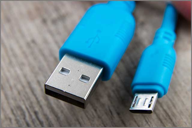
USB or Universal Serial Bus is a popular connector found in electronic devices. You can find them everywhere. Find them on computers, printers, pen drives, mobile phones, or even digital cameras. All the devices have a USB connector. It helps establish a connection with other accessories like computers and peripherals.
You can find different connectors like USB-A, USB-B, and USB-C based on the versions of USB. Connectors also come in male and female genders to ensure accurate connections. You will find the USB connectors fixed on the board or PCB of the device. It helps to form a connection between boards or devices.
Components of USB PCB Connectors
USB PCB connectors can have different components that include-
Contacts:
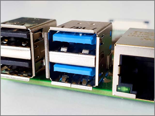
All USB PCB connectors come with a minimum of four contacts. Some connectors like USB 3.0 features five or more contacts to create a connection. The contacts include ground, power, and two data lines. USB connectors can transmit 5Volts, up to a maximum of 500mA.
You will find the contacts over a plastic bar.
Shielding:
USB PCB connectors can perform in environments that involve a lot of electrical noise. The shielding is of metal covering, which doesn’t form part of the electrical circuit.
Terminations:
USB PCB connectors may have pins or terminations at their bottom. It helps to fix them to the PCB without any trouble. Manufacturers use various methods like soldering to fix the pins to the board.
What USB PCB Thickness should You Use?
You will need to choose the right thickness of the USB PCB board to ensure smooth functioning. The standard PCB thickness of 1.6mm will work fine for most cases. However, a 2 mm thickness can be better for some applications.
Want to save the costs of a 2mm board? You can design the backside to accommodate additional shims to increase the thickness. Remember that the theoretical height of the plug to the contact from the outer shield is 2.235mm.
Types of USB PCB Connectors You can Choose From
A wide range of USB PCB connectors is available to suit various applications. Some of the common types of connectors include-
Vertical Mount Plug
You will find vertical mount USB PCB connectors made to fix them to a PCB vertically. You can mount these vertical plugs through various methods like through-hole or soldering. These plugs are ideal for cradle mounting applications. You can use them for charging multiple devices like smartphones and computers.
Vertical Through Hole
These connectors have a vertical orientation, just like vertical mount plugs. The terminations of the USB connectors pass through the plated thru holes of the PCB before fixing. Vertical through-hole connectors offer a narrow footprint for space-restricted applications.
Mid-Mount
Mid-Mount PCB connectors are suitable for low-profile consumer electronics. You find them useful when you are concerned about the height over and below the PCB. You can mount the connectors in the middle portion of the PCB using surface mount or through-hole method.
Top Mount
You can fasten the top mount USB connectors using the terminating leads on the top side of the PCB. Generally, you find the Top mount connectors onto the contact pads.
Bottom Mount
You will find that the bottom mount USB connectors are fixed to the bottom side of the PCB. These mainly use surface mount technology.
Types of USB Ports for PCBs
As we previously discussed, there have been different versions, standards and variations of PCB USB connectors and ports in the last few years. You may completely replace your USB port to address the problems you’re experiencing. If you do choose this path, you must be cognizant of the latest standards and ports available to you.
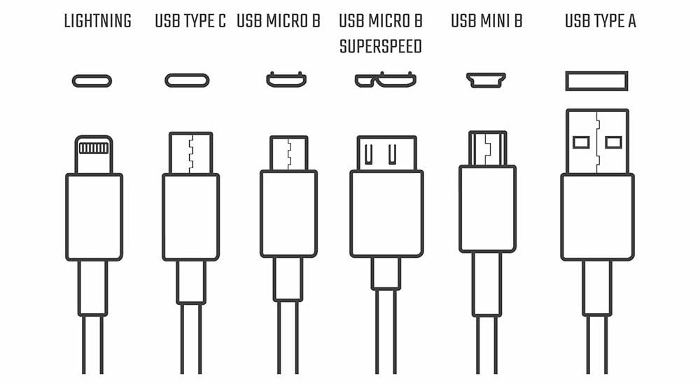
- USB Type A is currently the most widely used port type. It’s a rectangular port that allows only one way of connection and is found in smart TVs, computers, chargers, gaming consoles, etc.
- USB Type B: Far less common than Type-A port. You can mostly find it in home printers.
- USB Mini B: A miniaturized version of the USB Type B connector. It isn’t as widespread as it once was. You could find this port in older cell phones and other mobile devices until the USB Micro B and USB Type C replaced it.
- USB Micro B Superspeed is a highly compressed USB port. Since it supports high-speed data transfers, it’s typically used to connect portable or external 2.5” hard drives.
- Micro USB B was introduced to replace the mini USB B. It is still found in older portable devices and peripherals, such as smartphones and wireless headphones.
- USB Type C: Introduced to replace both the USB Type A and Micro USB ports. It supports high transfer speeds and reversible connections. You can find it in modern computer monitors, mobile devices, and computers.
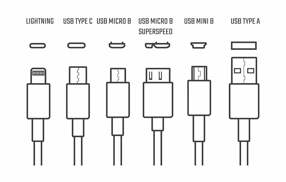
Usb Cables Icons Electronic Device Input Stock Vector
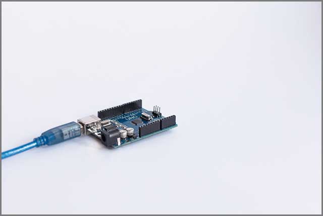
Micro Connectors on USB PCB- Can They Create Problems?
Sometimes you may need to mount USB micro connectors on your PCB. These connectors can be prone to weakness as you continually plug in and plug out cables or devices. With time, they may become loose or get wholly detached from the PCB. You can take the following measures to resolve the problem-
- Use the mid-mount or through-hole method for extra mechanical strength
- Take the help of a plug that you can place flat on the PCB.
- Use neutral cure silicon rubber or molten glue to add additional support
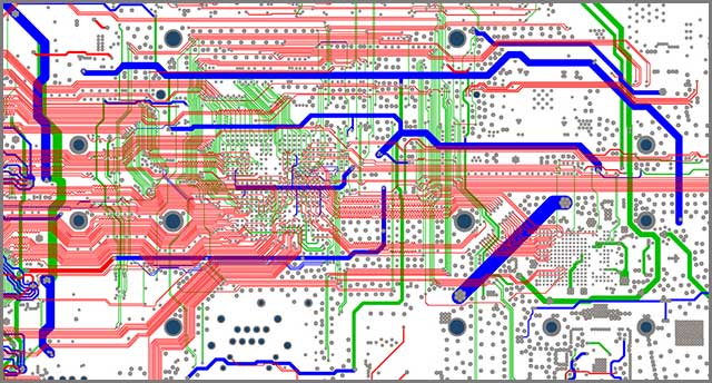
What Makes a PCB Layout Stop Working?
The design and layout of your USB PCB should be accurate and errorless for it to function smoothly. Various mistakes in the layout can give rise to complications and cause malfunctions and issues.
Incorrect landing patterns:
Mistakes are common while drawing a landing pattern. For example, you may get the pin-pin spacing wrong, making it difficult to solder the part on your board. To prevent such problems, try using the components in the library of your designing software.
Incorrect location of decoupling capacitors:
Improper placement of decoupling capacitors may also cause issues. Make sure the capacitors are placed on the power supply rail and closer to the pin receiving the voltage.
Insufficient power trace width:
Your traces need to have the proper width to carry the signal or power successfully. If you get your trace widths wrong, your whole application can suffer. Always stick to the minimum required widths and use a trace width calculator for correct measurements.
Common Problems of USB PCB
In this section, we will take a look at some common USB PCB problems and their solutions.
1. Faulty USB PCB Ports
Your USB PCB can cause errors or malfunction if you have a defective USB port. First, you need to determine whether the problem is with the port or the device. Plugin your device into another USB port and check if it works. If it does, then you can be sure that the USB port is out of order. If your device still doesn’t work, then it’s not the fault of the USB port.
You can try the following-
- Check and clean if any dirt has accumulated on the USB port.
- Do a physical check to see if the port is loose or broken.
- Restart your computer/laptop and see if the port works
- Check your device manager and uninstall the USB Host Controller.
- Replace USB port if everything else fails
2. Software Configuration Problems of USB PCB
Invalid software or operating system may also cause USB PCBs not to work. The problem may arise after you have changed your computer settings or installed a new operating system. You can follow the steps below to resolve the issue-
- Check the settings in Device Manager, Control Panel, or the main setup.
- Ensure you have the proper drivers installed
- Run a virus scan to check if your computer is healthy
3. Hardware Problems
Sometimes, your USB PCB problems can result from hardware failure or malfunctions. Your USB card can come loose from the expansion slots, or the slots can fail themselves. Some wires connecting the USB port to the motherboard may also become loose or detached. You may also encounter a defunct USB controller or ports.
Here’s what you need to do-
- Check your ports and connectors for dust and dirt.
- Run a physical check to determine if any wire or components are loose
- Replace faulty expansion slots, cables, or ports
4. Parts From Before
Your USB PCB may not work if you have previously connected a faulty device. Sometimes, rapid connection and disconnection of appliances can also cause the ports not to work. To address the issue-
- Shut down and restart your computer again
- Reconnect your device and scan for hardware changes
- Reset the USB Controller
5. Wrong Type of Extension Cable for USB PCB
Using the wrong type of USB extension cables may result in a USB PCB malfunction. That can happen when you use high-speed accessories with low-speed cables. Do the following-
- Choose the right USB extension cable.
- Check for USB type (A, B, C) to choose the proper cable.
- Read the user manual of your device for suitable cable types.
Benefits of Using USB PCB
You may elect to use another type of connector or port for your electronics or PCB project instead of a USB. For instance, you could integrate an Ethernet (RJ45 connector) or FireWire port. Both these connectors offer faster speeds than USBs (depending on the version). So, if you run into problems with your USB connector and port, why shouldn’t you replace it with an alternative?
USB Can Supply Power
The most obvious advantage that USB ports and connectors have over FireWire and Ethernet ports is their ability to supply power. FireWire and Ethernet, in their original forms, can only transfer data. As such, you cannot use the older forms of these connectors to charge or power devices.
Even ethernet enhanced with Power over Ethernet (PoE) cannot deliver the same amount of current over wire. The maximum current that the latest PoE standard can deliver is 600 mA, whereas the latest USB standard offers as much as 900 mA.
Most (if not all) Android devices feature a USB port and connector of some sort. Some computer speakers can be powered using USB. The number of devices that support charging or powering through PoE pales in comparison to the number of devices that support USB. This all ties into the next point…
USB is Well Supported
A vast number of devices have USB support of some sort. From modern TVs, computer screens to smart fridges and mobile devices. This makes it easier to find USB cables and connectors for your project.
In addition to this, USB ports are generally easy to connect and use. Depending on the security of the device, you can simply plug and play and connect your USB device.
Modern USB Ports are Super Fast
At the time of writing this guide, the latest USB specification was USB4 2.0. It can deliver transfer speeds as fast as 80 Gbps over USB-C. This makes it faster than 10 Gigabit ethernet and the latest FireWire standard.
Replacing your PCB’s USB
There are a few considerations to keep in mind as you’re replacing your PCB USB port. If you want the best results, it’s best to follow these steps:
- Decide on the USB standard
- Design a schematic for your PCB USB
- Select the type of USB port(s) and connector(s) you want to use with your PCB
- Lay out the traces (routing)
- Add grounding and shielding
- Incorporate the necessary power circuits (if necessary)
- Add Electrostatic discharge (ESD) protection and overcurrent detection
Conclusion
We have discussed the most common problems. Don’t worry about USB PCBs problems while using, designing, or manufacturing. You can avoid most of these problems by adopting a careful approach. Double-check to make sure you are committing no mistakes. It’s also equally important to ensure that your USB connectors are of high quality. You need a durable material for maximum performance and safety. Get your USB PCB components from a reliable manufacturer so that you can get complete peace of mind.
We can help you with high-standard USB PCB connectors with precision and quality.
