On Circuit Board Drill, Emerging PCB boards in electrical and electronic devices undergo a long, detailed process of designing, processing, and manufacturing before coming in their eventual form. Out of the many strategies that these PCB boards experience is the drilling process. During PCB fabrication, the designed PCB board needs a hole to be drilled into the board to sell sensors and components.
In the ancient days of PCB development, when PCB boards were designed on the surfaces such as wood and fiberglass, holes were made onto the board via nails and other sharp objects. However, those were not appropriate and efficient ways. It took some time for the engineers to develop an accurate solution for drilling precise and precise holes onto the PCB boards. In modern days circuit board drills are commonly used to perform drilling of spots onto the PCB board. Figure 1 shows a circuit board drill.
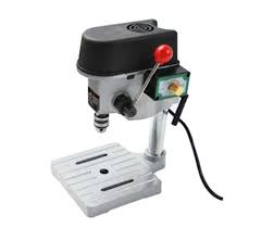
Figure 1
1.Circuit Board Drill
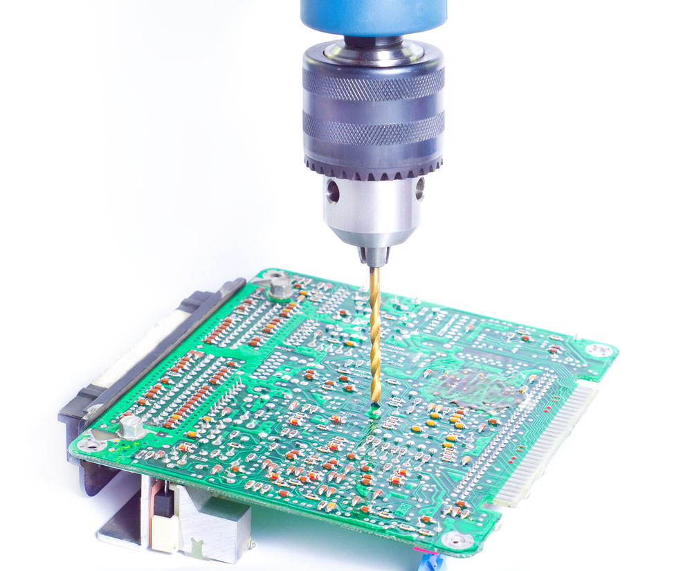
Market these days is full of circuit board drills of different colors, pins sizes, and qualities. The core objective of circuit board drills is to drill precise holes in fiberglass printed circuit boards, plastics, and other laminates. Circuit board drills are micro drills in actuality that aim at providing as much precision in drilling as possible. Circuit board drills provide ample rigidity and longer tool life despite being exposed to high temperatures and abrasion. Customarily the circuit board drills possess a drill diameter equal to shank diameter to get smooth burr-free performance. Yet, many other drill sizes are available for the user’s convenience. Figure 2 shows a PCB board undergoing the process of drilling.
2.Process of circuit board drilling
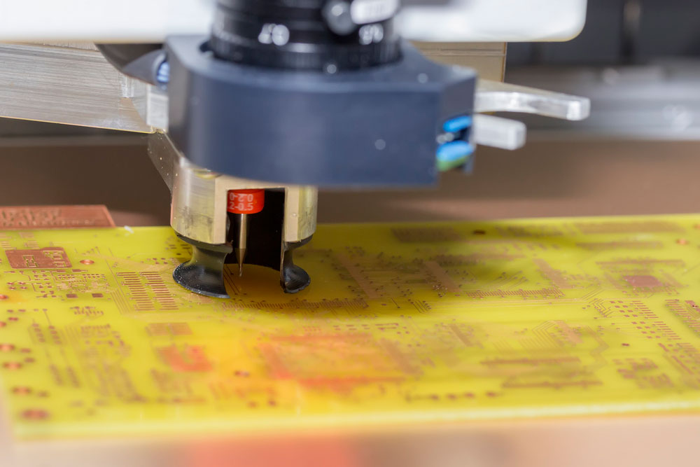
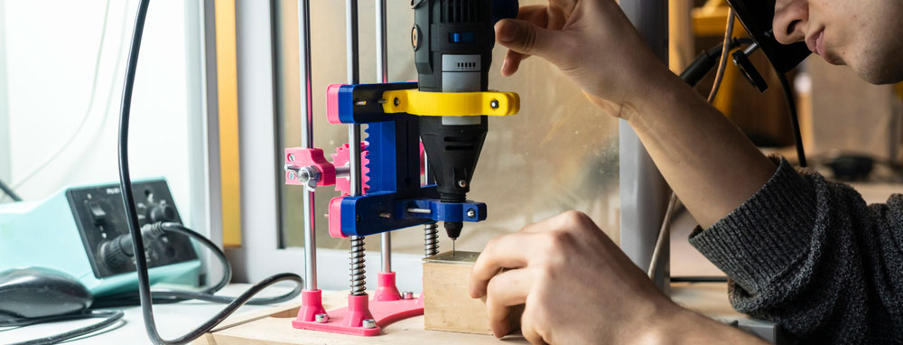
To perform drilling of a PCB board, the engineer must first use an X-ray drill to locate the target points in the copper of the inner layer so that it gets easier to identify which issues need to be drilled over the board. Initially, the machine drills registration holes for identification marks for the user to hit them later until the inner layer pads center.
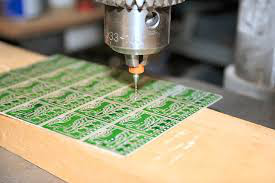
Secondly, to set the circuit board drill, the user places the panel of exit material on the drill bed, which targets refraining the exercise from tearing the copper foil as it passes through the PCB board. Later further PCB panels along with aluminum entry foil are added to the drill bed. Circuit board drills provide a lot of drill sizes options to the user so that the holes could be drilled on the PCB board as per users’ requirements. Figure 3 shows the various circuit board drills.
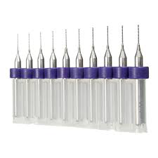
Figure 3
Conclusion
Circuit board drill seems like a tedious task, yet it holds immense significance in designing PCB boards as at the end of the functionality of the PCB board is being influenced by the holes that connect the components to the board. With the advent of modern circuit board drills, drilling spots onto the PCB board has become an easier task for designers.