


A printed circuit board (PCB) is essentially a collection of copper traces running through a substrate. Consequently, it serves as the foundation for most electronic devices. However, it’s virtually useless without the electric circuit board components that connect through it. Thus, if you’re building an electronics project with a circuit board as its base, you need to understand all the components available to you. Additionally, you need to understand what they do. The following guide will explore and discuss all the various components of a circuit board parts. After PCB assembly, this should make building your next project easier.
Circuit Board Parts Identification
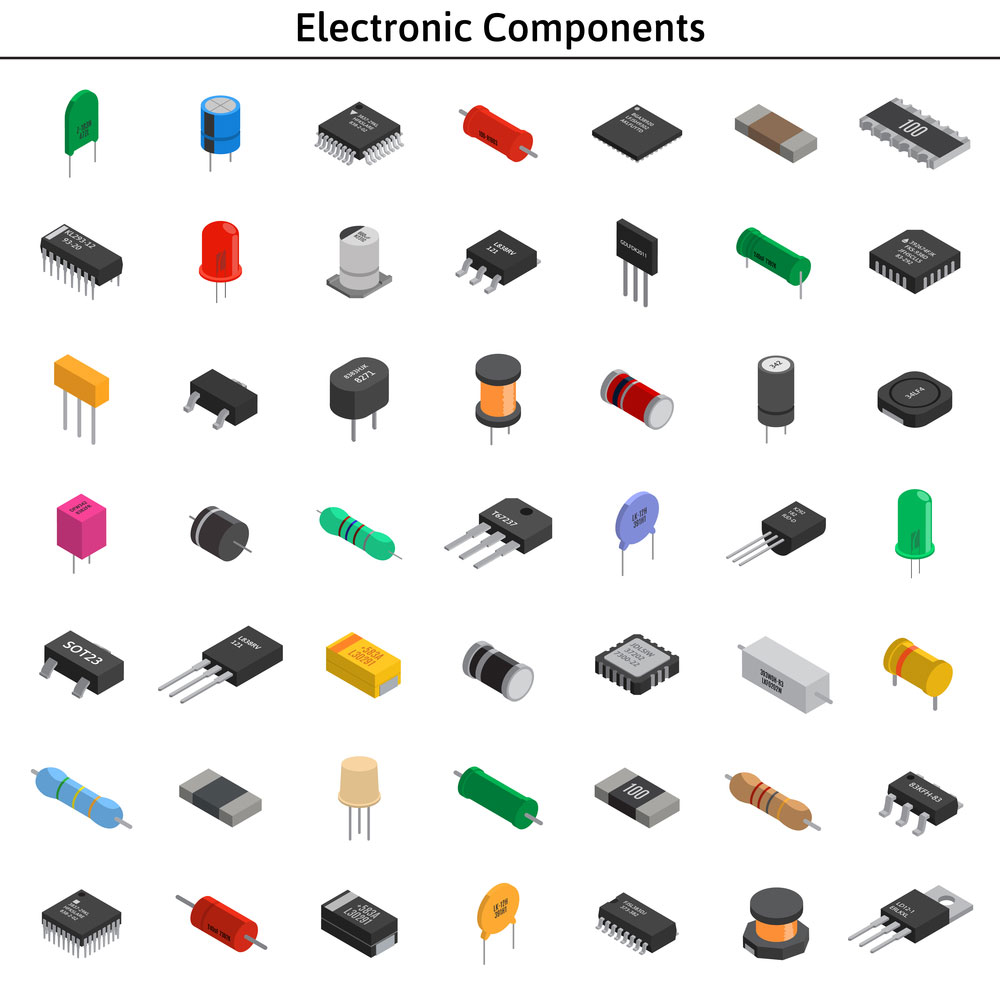
various unlabeled isometric electronic components
Essentially, the electronic components on a circuit board control and modify input currents and output them to power separate devices for different purposes. Accordingly, you can use your circuit board to create something as simple as a battery charger or use it as a base for something as complex as a computer’s motherboard.
Regardless, you’ll need to be able to identify the core components of the circuit board. Most components are generic. Therefore, you can simply purchase them from any electronics store. And we often label and color code these components according to their value or power to make it easier.
However, you may find that you’ll need specialized components for your project. Thus, most electronic components manufacturers can produce them according to your specifications.

different electronic components
Before deciding which electronic components to use for your project, you’ll need to draft or follow a circuit diagram or electronics schematic. Fortunately, resources are abundant on the internet that shows you how to create and read one.
Once you’ve reached full literacy, we suggest you learn the basics of converting a schematic to a PCB layout. Additionally, you can use various software tools to create your own diagrams, such as Scheme-It and EasyEDA.
Nevertheless, you’ll need to know how these components look and function before you learn how you place and connect them in your design. So, this is what we’ll cover in this section.
1. Circuit Boards
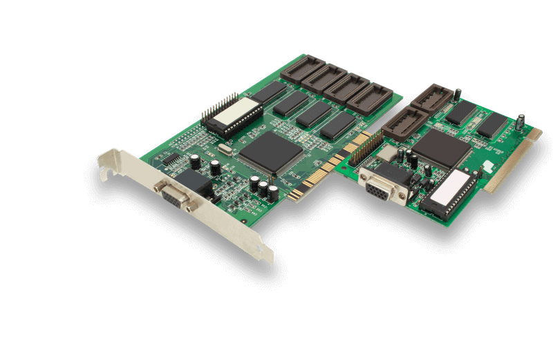
The most important component of the circuit board is the circuit board itself. There are different types of circuit boards, and each has its own assembly requirements. Thus, selecting the right one for your project is important. Besides, it will determine how your final product will cost and weigh. Nevertheless, the reference designator for a separable circuit board assembly is A.
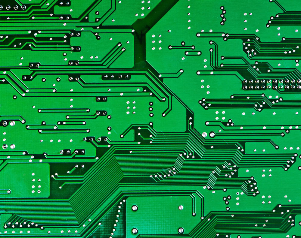
Simple Image of a plain green printed circuit board
2. Resistors (Fixed Value)
Resistors are one of the simplest and most used electronic components. Plus,they are two-terminal passive components that we primarily employ to reduce current flow. Furthermore, they come in various materials, values, and sizes.We measure the amount of electrical resistance of a resistor using Ohms. Usually, you can identify the resistance value by the resistor’s color codes and labels. The reference designator for resistors is R. Furthermore, the most common type of resistor is the fixed value resistor. However, variable resistors are also available.
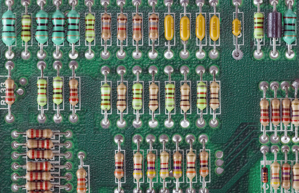
circuit board with multiple resistors
3. Variable Resistors
Variable resistors allow you to change their value or strength of resistance manually. Besides, they usually come with a dial or slide, which you can use to control the amount of resistance. Nevertheless, the most common types of variable resistors include:
- Potentiometers
- Rheostats
- Digital Resistors
- Presets
The reference designator for a variable resistor can be RV, VR, or just R.
4. Capacitors
A capacitor temporarily stores electrical energy. Then, it disperses this charge when any part of the circuit requires it. Much like resistors, they are two-terminal passive electronic components. You can easily identify them according to their drum shape. Additionally, they come in various color codes – another attribute that they share with resistors. We use capacitance to measure the value of the capacitor. Finally, the reference designator for a capacitor is the letter C.
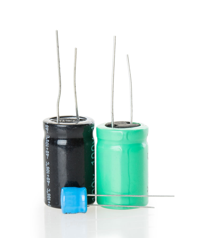
Image of three capacitors with different sizes and colors
5. Transistors
A transistor is a multi-terminal (often three-terminal) semiconductor that either amplifies or reduces electrical signals and electric current. There are three main types of transistors:
- Bipolar Junction Transistors (BJTs)
- Field-Effect Transistors (FETs)
- Insulated-Gate Bipolar Transistors (IGBTs)
Incidentally, the most common transistor is the bipolar junction transistor. People often confuse transistors with resistors. While their functions overlap, they serve different purposes. Commonly, we use them as electronic switches. Nevertheless, along with their symbol, the reference designator is a T on the electronic schematic.
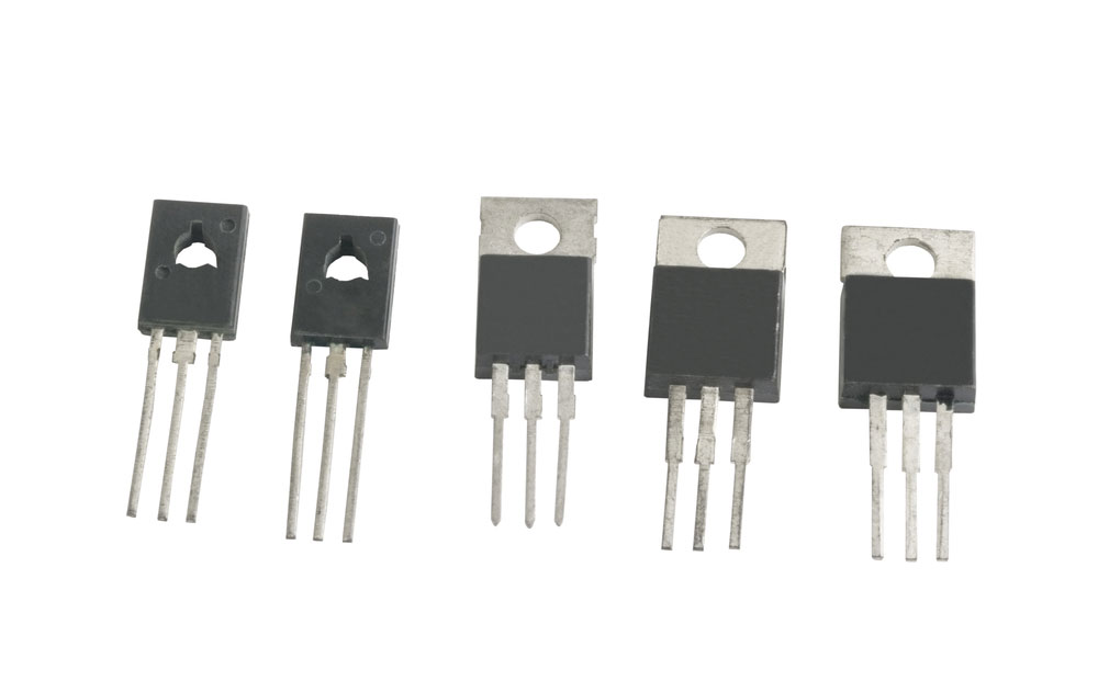
A collection of unmarked transistors
6. Inductors
Inductors have a similar function to capacitors. Adjacently, they are passive dual-terminal components that store electrical charge in a magnetic field. Primarily because of their appearance, people often refer to them as coils, chokes, or reactors. Inductors typically comprise a wire wound into a coil. Consequently, they are one of the most distinct PCB components and are generally easy to identify. Finally, the reference designator for an inductor on a circuit diagram is L.
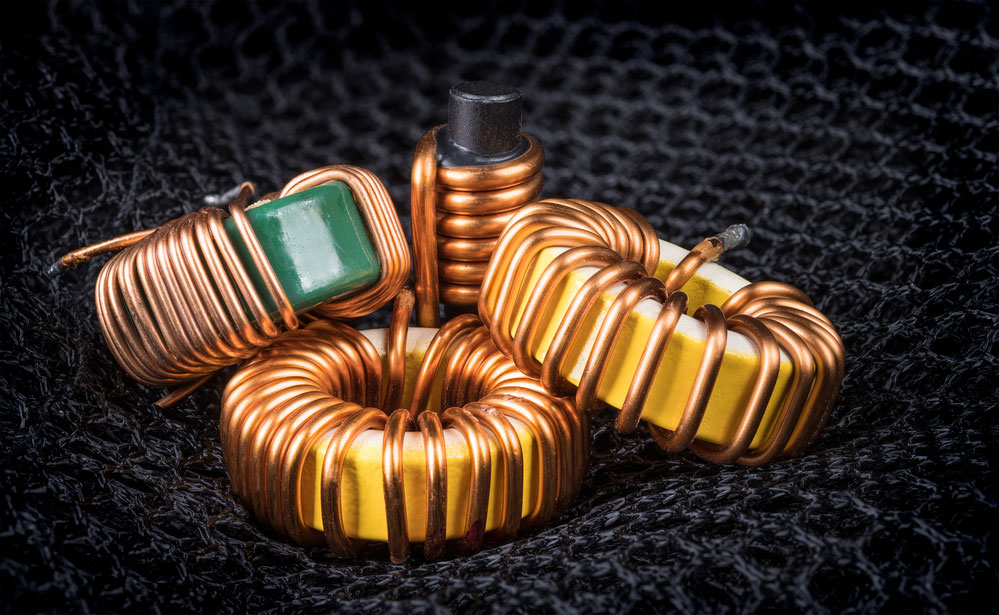
An image depicting a group of coils with magnetic cores and copper winding
7. Diodes
Diodes are two-terminal passive devices that allow current to flow through them in only one direction. Expectedly, there are a variety of different diodes on the market. The most common being:
Each diode has its own purpose and function. For instance, some diodes may act as an electromagnetic switch (PN junctions), while others may function as a light source (LEDs). Accordingly, we identify different diodes using dEach diode has its own purpose and function. For instance, some diodes may act as an electromagnetic switch (PN junctions), while others may function as a light source (LEDs). Accordingly, we identify different diodes using different symbols and lettering. Specifically, the reference designator for a generic diode on a circuit diagram is D. However, we sometimes use LED to denote light-emitting diodes on an electronic schematic.
8. Fuse
Fuses protect your electrical circuit from excess current (overcurrent), which may lead to overheating. Commonly, the fuse looks like a clear cylindric piece of glass(silicon), clad by metal on each side and a coil running through its interior. However, the middle section of the fuse isn’t always transparent. In most cases, it’s white. Nevertheless, if your circuit handles a large amount of current, you benefit from integrating a fuse into it. The reference designator for a fuse is F.
9. Integrated Circuit
As the name implies, integrated circuits (often called chips) are miniature electronic circuits usually comprising a semiconductor material. Commonly, they consist of hundreds of tiny transistors. Microprocessors are the most well-known integrated circuits. The reference designator for an Integrated circuit is U.
10. Electronic Oscillator
We use electronic oscillators to convert direct current (DC) into alternating current (AC). The electronic oscillator produces periodic electronic signals in the form of a sine, square, or triangle wave. Nonetheless, crystal oscillators (crystals) are the most common types of electronic oscillators. They use vibrating quartz crystals to produce an electrical signal with a constant frequency. The reference designator for oscillators is either XTAL or Y.
11. Ceramic resonators
Resonators work similarly to electronic oscillators. Comparatively, when we use them in an oscillator circuit, they produce a fluctuating signal with a specific frequency. They consist of a piezoelectric ceramic material. The reference designator for a ceramic resonator is X.
12. Transformers
The next PCB component on our list is the transformer. A transformer is a passive static electronic component that transfers alternating electric current from one circuit to another at an identical frequency. Consequently, it has no moving parts, which is why we call it a static component.
As such, most transformers consist of two electric circuits which link together through a single magnetic circuit. Thanks to this magnetic circuit, the transformer is capable of transferring currents at the same frequency. Nevertheless, transformers are available in THT or SMD packaging. The reference designator for a transformer is T.

Current transformer, by Hannes Grobe, licensed under CC BY-SA 4.0
13. The Relays
Relays are one of the simplest components and yet one of the most significant. They allow digital circuits and digital microcontrollers to switch high-powered devices on and off. Accordingly, a basic relay consists of a coil that builds up a magnetic field when the current passes through it.
Thus, if we run a small amount of power on its magnetic coil, it magnetically pulls a switch into the closed position. Consequently, this will allow electron current to flow from the other side of the electric circuit. The relay’s reference designator is K.
14. Switch
We use switches every day to control our electronic devices. Electric circuits require a closed-loop for electricity to flow through them. Inversely, if this loop has an obstruction or a break, it prevents current from flowing. Nevertheless, a switch can be momentary or maintained. A maintained switch will maintain its state until it actuates into a new one. Conversely, a momentary switch will make or break a connection when a user actuates it (presses and holds it). However, it will go back to its default state as soon as the user releases it. The reference designator for a switch is S.
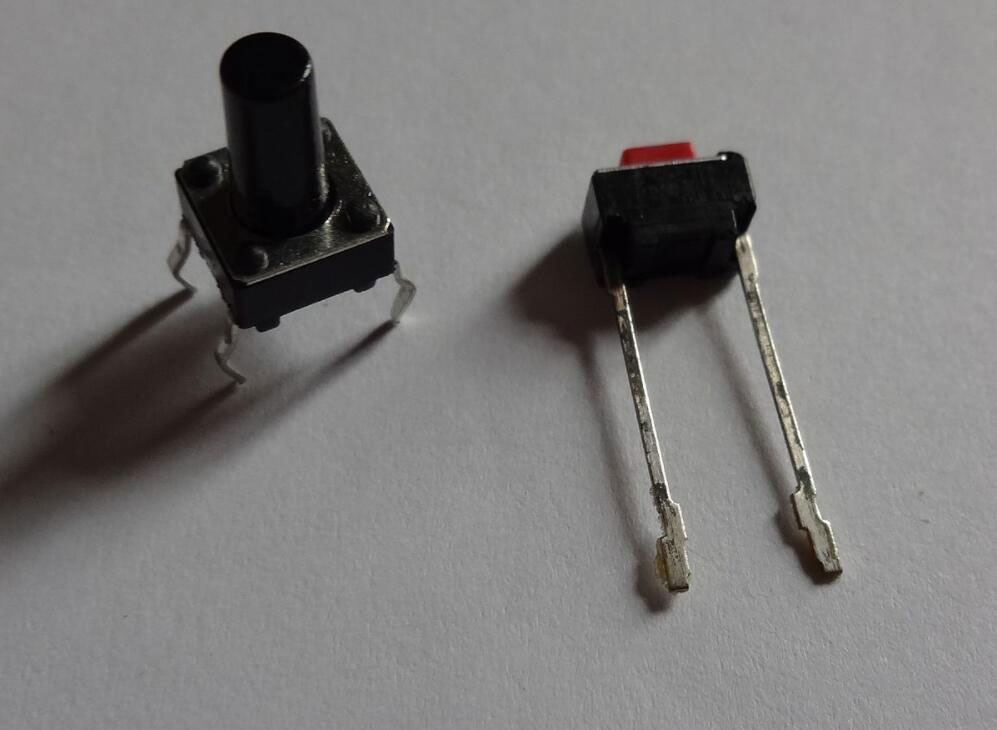
Two micro switches, by Vahid alpha, licensed under CC BY 3.0
15. Connectors
Connectors allow you to connect your circuit board to external input and output devices. Alternatively, they allow you to interface your primary circuit board with other circuit boards. Justifiably, people may refer to them as interconnects.
There are many different types of connectors available for your circuit board. Often, they can range from backplane connectors to jacks and JST connectors. The Reference designator will depend on the type of connector. For instance, a jack will use J, while a socket connector will use X. A plug connector will use P.
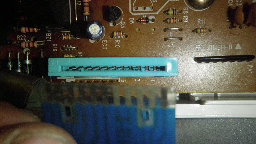
PCB mount connector, by Jstapko, licensed under CC BY-SA 3.0
Circuit Board Parts Placement
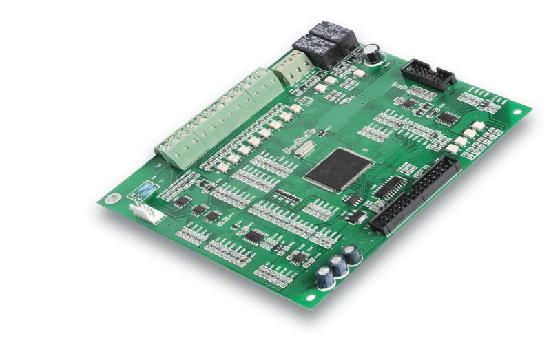
During the PCB assembly process, manufacturers can mount or place circuit board components in two ways – using through-hole technology or surface mount technology. Additionally, components such as integrated circuits can come in a variety of packages which will dictate how we mount or place them. Nevertheless, in this section of the guide, we’ll discuss your circuit board mounting, placement, and component packaging options.
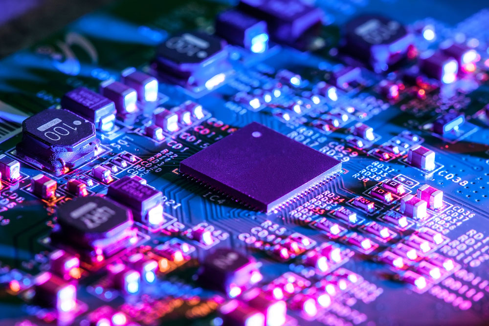
Image of a circuit board
Through-Hole Technology (THT)
During the early popularization of printed circuit boards, through-hole (colloquially “thru-hole”) technology was the electronic and PCB assembly technique. Commonly, we sometimes refer to through-hole technology as through-hole mounting (THM).
Nevertheless, in this assembly technique, a manufacturer or engineer will drill holes into the circuit board and then insert the component into it. We call these holes “through-holes,” and this is where the mounting technique gets its name. Accordingly, we use leads to connect the electronic component to the through-hole.
Once we’ve inserted the lead, we solder it to a set of pads on the other side of the board. Furthermore, we can do this manually (by hand) or by using an automated mounting machine.
Surface-Mount Technology (SMT)
Surface-face mount technology is an assembly technique where manufacturers produce electronic circuits that allow on-surface mounting of electronic components on PCBs. Consequently, we refer to electronic components that follow SMT as surface mount devices (SMD).
Today, surface-mount technology seems to be more popular than THT because it is a cheaper and more reliable PCB assembly technique. However, manufacturers will often combine the two because some components are only available in through-hole packages while others are only available as SMDs.
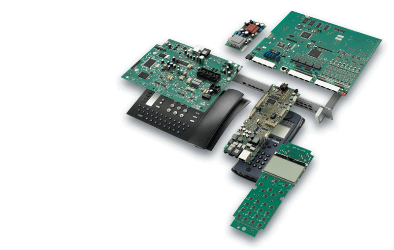
Integrated Circuit Packaging Types
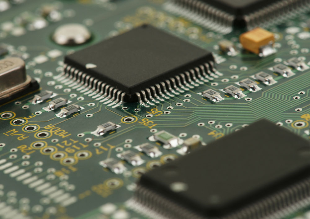
Picture of chip/integrated circuit on a printed integrated circuit board
Integrated Circuits come in a variety of packages. Accordingly, these packages offer protection and allow manufacturers to mount them during the manufacturing process. Nevertheless, types of IC packaging and their most common subtypes include:
Through-hole packaging
- Single in-line package (SIP)
- Dual-in-line package (DIP)
- Zig-zag in-line packaging (ZIP)
Surface mount packaging
- Column-grid array (CGA)
- Ceramic column-grid array (CCGA)
- Ceramic package (CERPACK)
- Lead-less lead-frame package (LLP)
- Land grid array (LGA)
- Low-temperature co-fired ceramic (LTCC)
- Multi-chip module (MCM)
- Micro surface-mount device extended technology (MICRO SMDXT)
Chip carrier packaging
- Bump chip carrier (BCC)
- Ceramic lead-leas chip carrier (CLCC)
- Lead-less chip carrier (LCC)
- Leaded chip carrier (LCC)
- Leaded ceramic-chip carrier (LCCC)
- Ceramic dual lead-less chip carrier (DLCC)
- Plastic leaded chip carrier (PLCC)
Pin grid array packaging
- Organic pin-grid array (OPGA)
- Flip-chip pin-grid array (FCPGA)
- Pin array cartridge (PAC)
- Pin-grid array (PGA)
- Ceramic pin-grid array (CPGA)
Flat packaging
- Ceramic flat-pack (CFP)
- Ceramic quad flat-pack (CQFP)
- Bumpered quad flat-pack (BQFP)
- Dual flat-pack (DFN)
- Exposed thin quad flat-package (ETQFP)
Small outline packaging
- Small-outline package (SOP)
- Ceramic small-outline package (CSOP)
- Dual small-outline package (DSOP)
- Thermally-enhanced small-outline package (HSOP)
- Small-outline J-leaded package (SOJ)
Chip scale packaging
- Beam lead technology (BL)
- Chip-scale package (CSP)
- True-chip size package (TCSP)
- True die-size package (True die-size package)
- Chip on board (COB)
- Chip-on-flex (COF)
- Tape-automated bonding (TAB)
- Chip on glass (COG)
Ball grid array
- Fine-pitch ball-grid array (FBGA)
- Low-profile ball-grid array (LBGA)
- Thin ball-grid array (TBGA)
- Organic ball grid array (OBGA)
- Plastic ball-grid array (PBGA)
The above includes only a sample of IC and electronic component packages. If you want to learn more, please visit our guide on IC packaging.
How to Choose The Right Electronic Circuit Board Parts
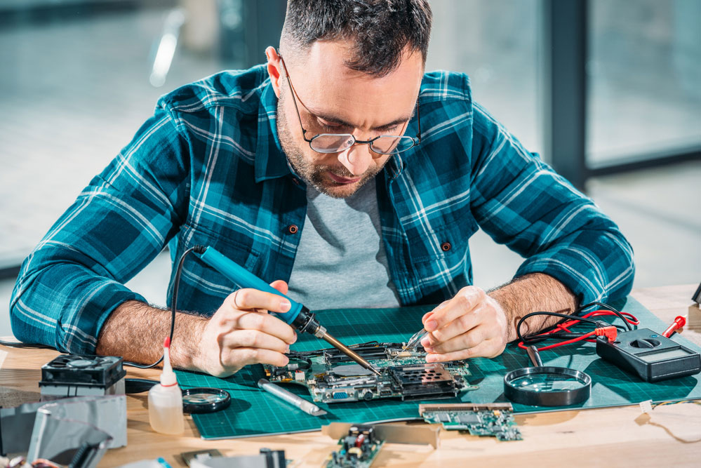
Hardware engineering soldering parts
The first thing you need to do is plan your project out carefully. Indeed, this entails understanding how you’ll use your board. Nonetheless, a fully functioning PCB requires a plethora of components and parts to function effectively.
We previously spoke about drafting a schematic diagram. Consequently, this will allow you to figure out the component placement, spacing, values, and size of your components.
Next, you’ll need to decide what type of mounting you’ll use on the board, which will determine the package types for your components.
Additionally, the components will have to meet your soldering requirements and methods. If you’re soldering through automation or an oven, your components should be conducive to these methods. As such, in addition to picking the right components, you’ll need to pick the right dielectric material for your circuit board. It should also be suitable for your mounting and soldering techniques.
Nonetheless, the requirements for manufacturers won’t be the same for individual hobbyists. While a manufacturer will look for a supplier that mass produces components, individuals may decide to use a general electronics store. Furthermore, manufacturers may require custom-made components. Thus, selecting the right supplier is an important part of eventually sourcing the correct components for your PCB.
Finally, you should consider the price of your components. This will entail understanding the electronics market and finding the right suppliers. While you may find suppliers who can source you with electronic components that ultimately meet your specs, this does not mean their prices are reasonable.
You’ll need to exercise some discretion when selecting your PCB components. Nevertheless, these are only just a few tips for choosing your PCB components.
Conclusion
Without its electronic components, the circuit board can’t do very much. In the above text, we explored and examined the various components of a circuit board. Additionally, we explained what you need to consider while shopping for your parts. We hope you’ve found this guide to be helpful. As always, thank you for reading.g.